INTRODUCTION:-
The main basic principle in which a push pull amplifier operates is that the input signal is converted before amplification into two separate signal which are identical except is 180 degree phase difference.
In short term:-
- Push pull amplifier means it works only one transistor in first half cycle.
- And second works in other half cycle.
- In this circuit two identical transistor are used.
- When Q1 transistor are in forward bias means conduct conducting ,or current flows through it ,at those time other Q2 transistor are off means reverse bias.
- When Q2 transistor are in forward bias means conduct conducting ,or current flows through it ,at those time other Q1 transistor are off means reverse bias.
 |
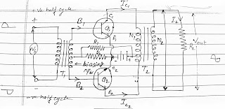
| Circuit diagram of CLASS A push pull amplifier |
Each signal is applied as the input in one of transistor of push pull amplifier circuit.
The output transformer is connected to the collector circuit of the transistor in such away that the collector current of two transistor provide an overall signal having the same waveform as the input signal.
Circuit arrangements:-
Push pull amplifier uses two identical transistor Q1 and Q2. The emitter terminal of two transistor Q1 and Q2 are connected together. The input signal is applied to the input of the two transistor through Centre tapped Step Up Transformer T1, which provide opposite polarity signal to the two transistor input. The collector terminal of the both of the transistor are connected to the end terminal of centre tapped primary of the output transformer T2 .
The power supply Vcc connected to the emitter terminal and Centre tapped of primary of output transformer. Register R1 and R2 are used to provide proper bias for the circuit. The load RL is connected across secondary of the output transformer. The turn ratio 2N1= N2 of the output Transformer is choosen so as to match the load with the output impedance of the amplifier and therefore it transfer maximum power. The quicescent current of two transistor which are equal in magnitude follow in the opposite direction through each half of the primary of the output Transformer T2.
WORKING:-
AC signal is applied to the input. When the input signal voltage is positive, the base off transistor T1 is more positive while the T2 is less positive.Hence the collector current IC1 of transistor T1 increases and that of T2 decreases Ic2 .These terminal flow in the opposite direction in two half of primary of the output Transformer more volver the flux produced by the current will be in oppsitive direction. As a result the voltage across the load will be induced voltage whose magnitude will be proportional to the difference of collector current and vice- versa.


0 Comments